Welcome to BEAM! Tel: +86-553-5896615
Language: Help
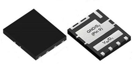
MOSFETs SIZ988DT-T1-GE3
Vishay
SIZ988DT-T1-GE3
--
Diodes, Transistors and Thyristors
MOSFETs

Specification
| Product Attribute | Attribute Value |
| HTS | 8541.29.00.95 |
| PPAP | No |
| EU RoHS | Compliant with Exemption |
| Mounting | Surface Mount |
| ECCN (US) | EAR99 |
| Packaging | Tape and Reel |
| Pin Count | 8 |
| Automotive | No |
| Lead Shape | No Lead |
| PCB changed | 8 |
| Part Status | Active |
| Channel Mode | Enhancement |
| Channel Type | N |
| Configuration | Dual |
| Package Width | 6 |
| Package Height | 0.7(Max) |
| Package Length | 5 |
| Product Category | Power MOSFET |
| Supplier Package | PowerPAIR EP |
| Maximum IDSS (uA) | 1 |
| Process Technology | TrenchFET |
| Typical Fall Time (ns) | 5|7@Channel 1|10@Channel 2 |
| Typical Rise Time (ns) | 10@Channel 1|10|15@Channel 2 |
| Number of Elements per Chip | 2 |
| Maximum Gate Resistance (Ohm) | 3.2@Channel 1|3.4@Channel 2 |
| Minimum Gate Resistance (Ohm) | 0.4@Channel 1|0.3@Channel 2 |
| Maximum Power Dissipation (mW) | 3800@Channel 1|4800@Channel 2 |
| Typical Gate Charge @ 10V (nC) | 14.3@Channel 1|34@Channel 2 |
| Typical Gate Charge @ Vgs (nC) | 6.9@4.5V|14.3@10V@Channel 1|15.4@4.5V|34@10V@Channel 2 |
| Maximum Gate Source Voltage (V) | 20 |
| Typical Output Capacitance (pF) | 280@Channel 1|730@Channel 2 |
| Typical Turn-On Delay Time (ns) | 10|20@Channel 2|15@Channel 1 |
| Maximum Drain Source Voltage (V) | 30 |
| Typical Gate Plateau Voltage (V) | 2.9@Channel 1|2.2@Channel 2 |
| Typical Turn-Off Delay Time (ns) | 15@Channel 1|25|27@Channel 2 |
| Maximum Diode Forward Voltage (V) | 1.2 |
| Typical Diode Forward Voltage (V) | 0.77@Channel 1|0.8@Channel 2 |
| Typical Gate to Drain Charge (nC) | 1.6@Channel 1|2.6@Channel 2 |
| Maximum Gate Threshold Voltage (V) | 2.4@Channel 1|2.2@Channel 2 |
| Minimum Gate Threshold Voltage (V) | 1.2@Channel 1|1.1@Channel 2 |
| Typical Gate to Source Charge (nC) | 2.8@Channel 1|5.8@Channel 2 |
| Typical Reverse Recovery Time (ns) | 19@Channel 1|31@Channel 2 |
| Maximum Operating Temperature (°C) | 150 |
| Minimum Operating Temperature (°C) | -55 |
| Maximum Continuous Drain Current (A) | 40@Channel 1|60@Channel 2 |
| Operating Junction Temperature (°C) | -55 to 150 |
| Typical Input Capacitance @ Vds (pF) | 1000@15V@Channel 1|2425@15V@Channel 2 |
| Typical Reverse Recovery Charge (nC) | 7@Channel 1|19@Channel 2 |
| Maximum Drain Source Resistance (MOhm) | 7.5@10V@Channel 1|4.1@10V@Channel 2 |
| Maximum Gate Source Leakage Current (nA) | 100 |
| Maximum Positive Gate Source Voltage (V) | 20 |
| Maximum Pulsed Drain Current @ TC=25°C (A) | 70@Channel 1|140@Channel 2 |
| Maximum Power Dissipation on PCB @ TC=25°C (W) | 3.8@Channel 1|4.8@Channel 2 |
| Typical Reverse Transfer Capacitance @ Vds (pF) | 34@15V@Channel 1|65@15V@Channel 2 |
| Maximum Continuous Drain Current on PCB @ TC=25°C (A) | 17.5@Channel 1|27@Channel 2 |
| Maximum Junction Ambient Thermal Resistance on PCB (°C/W) | 68@Channel 1|57@Channel 2 |
| Description |
Related products
Inquiry Price
Popular Products
Beam Electronics is a one-stop platform for electronic components from overseas sites under the "BEAM TECHNOLOGY COMPANY LIMITED" (supporting online ordering and trading). Beam Electronics is committed to building an efficient overseas intelligent IC components trading platform, the main business scope of overseas regions! With the wisdom of data-driven services, the company aims to improve procurement efficiency for the midstream and downstream enterprises in the IC industry, and is determined to become a reliable one-stop procurement platform for overseas IC supply chain.

Tel:+86-553-5896615
Email:sales@beamelec.com
Executive offices:Nianshi Industrial Park, No. 19 Qiluoshan Road, Jiujiang District,Wuhu, Anhui Province
8:30am to 12pm and 1:30pm to 6pm, Monday through Friday, UTC/GMT +8.